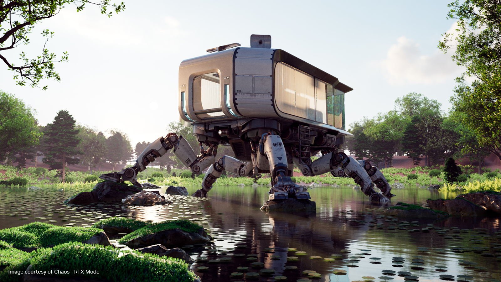
Real-time ray tracing is a powerful rendering technique that can create incredibly realistic images. NVIDIA OptiX and RTX technology make this possible, even for scenes with a massive amount of detail. However, when these detailed scenes involve movement and animation, maintaining real-time ray tracing performance can be challenging.
This post explores how the new RTX Mega Geometry features of NVIDIA OptiX 9, particularly Cluster Acceleration Structures (CLAS), enable fast ray tracing of dynamic, high-density geometry. Particular attention will be given to subdivision surfaces. Open-source sample code demonstrating the CLAS API in OptiX and concepts described in this post are available in the NVIDIA/optix-subd GitHub repository.
The challenge of dynamic scenes
NVIDIA OptiX on RTX hardware is capable of ray tracing large scenes in real time at one sample per pixel, provided that the geometry doesn’t change. This is possible for extremely dense geometry, even approaching the density of pixel-sized microtriangles.
However, scenes with this level of density that change on every frame present new challenges. The geometry acceleration structures—the search trees that RTX hardware uses to match triangles with rays—must be kept up to date, which may take longer than the tracing itself.

Sometimes you can take a shortcut: if the vertex positions change but the number of triangles and their connectivity stay the same, OptiX has a refit operation for acceleration structures. A refit reuses most of the existing search tree, so it is much faster than a full rebuild. But there are limitations: the time to trace a ray against the acceleration structure gets slower if the vertices move around too much. There is also the fundamental constraint that triangles can’t be added, removed, or reconnected in different ways, as these operations invalidate the tree.
NVIDIA OptiX 9 introduces a new data structure, the Cluster Acceleration Structure (CLAS). The inputs to a CLAS are small clusters of triangles defined by the user, and the CLASes become the inputs for a Cluster Geometry Acceleration Structure (Cluster GAS) that is quite similar to an existing GAS.

For certain types of scenes, a CLAS can provide the speed of a refit, while retaining most of the flexibility and trace performance of a full rebuild. The idea in a nutshell is to reuse patterns at the cluster level in a similar way as refit, and then do a full rebuild only over the clusters.
There are two types of possible cluster reuse. First, the same clusters can be reused, even perhaps with animated vertices, across frames. This is similar to the existing GAS refit and might be a good way to use clusters in a streaming level-of-detail system.
Importantly, the same cluster pattern can also be reused spatially within the same frame if multiple clusters have the same topology (pattern of vertices), just with different positions. This spatial reuse is primarily the focus here, as it is well-suited to dynamic tessellation of subdivision surfaces.
Subdivision surface basics
Catmull-Clark subdivision surfaces (subds) are a common way to represent geometry in animated feature films, and perhaps in games in the future. They consist of a control mesh made mostly of quads, along with a set of mathematical rules for subdividing the quads into a smooth limit surface. Any point on the control mesh can be evaluated using an optimized GPU method, and mapped to the limit surface, allowing for unlimited microtriangle density. Furthermore, high frequency detail can be stored efficiently in a separate displacement map along with other textures.

This representation has a number of advantages in a film or game production pipeline. Sculpting, rigging, animation, and so on can deal with just the control mesh, which is typically lightweight. And tessellating the limit surface on the fly for rendering means that the geometry density can be targeted to the camera. Surfaces that are off-screen or hidden can be tessellated at a lower rate.
Real-time tessellation
Figure 4 shows what an adaptive tessellation pipeline might look like for a renderer using OptiX with cluster geometry. This pipeline would run every frame, re-tessellating each dynamic mesh and rebuilding its acceleration structures.

The first few steps happen in user-space code, typically implemented as CUDA kernels.
- Animation or skinning: Animate the vertices of the subd control mesh.
- Tessellation and displacement: Define clusters on the subd limit surface, at a density of about one triangle per pixel. Save the cluster descriptions, and cluster vertices, into device buffers.
The acceleration rebuild and rendering steps are largely handled by OptiX.
- CLAS instantiation: Create a CLAS for each cluster using the descriptions and vertices as input. Note that this is a single function call that takes almost all its arguments in device memory.
- GAS and IAS build: Finish building the higher level accels. Since the leaves of the GAS are clusters, not triangles, this step is 10x-100x faster than it would be otherwise.
- OptiX launch: Shoot rays into the scene and shade them. OptiX provides the cluster ID and the vertices of the hit triangle as shading context.
With dense enough geometry, the microtriangle facet normals can be used directly as the shading normals; or optionally, limit normals can be evaluated during tessellation and passed to the path tracer in a buffer.
Spatial cluster reuse
When tessellating a surface such as the torus in Figure 5, you can intentionally tessellate clusters similarly or identically, to provide opportunities for spatial reuse. The quad-based control cage works in your favor here. Most of the resulting clusters are rectangular grids, many with the same MxN resolution.

A reusable cluster in the OptiX API is called a Cluster Template. It stores everything about a CLAS except for its vertices. It can be quickly instantiated over and over just by providing new vertices with the same topology (analogous to refit).
Cluster Templates can be created and reused for any triangle indices (Figure 6, left). However, because grid patterns are so useful for subdivision surfaces and other cases, OptiX has a separate API call for creating templates from grids (Figure 6, right). The grid version is not only simpler to use, since you don’t have to provide the grid template’s topology, but the resulting cluster template is often smaller and faster to ray trace, since OptiX may optimize for the predefined topology. See the OptiX 9.0 Programming Guide for API details.

This makes the overall frame time faster because:
- Many CLASes within the scene use the same cluster pattern (Cluster Template).
- Cluster Template precomputes most of the work of the CLAS build.
- The GAS built over CLASes has on the order of 100x fewer entries than if it were built directly over microtriangles.
Overall, Cluster Templates can speed up the acceleration rebuild by an order of magnitude versus putting all the triangles into a single flat GAS.
DLSS Ray Reconstruction
The overall pipeline shown in Figure 4 ends with an OptiX launch that traces the scene at about one sample per pixel to maintain high frame rates. A classic OptiX application for final frame lighting in film, for example, would accumulate 16-32 such frames to get a more converged image, and then run a denoiser to remove remaining Monte Carlo noise. This method becomes much more complex if the camera and geometry are fully animated.
You can instead replace the user-space accumulation loop with DLSS Ray Reconstruction (DLSS-RR), which does its own internal accumulation with the help of motion vectors and other input guide layers. DLSS-RR does not converge to a reference image, so it’s not appropriate for all users, but it does produce a stable, visually smooth image.
To compute accurate motion vectors for subds, the control cage from the previous frame is needed, along with the hit points for the current frame. For details on how to do this, see the example source code for cluster-based tessellation using CUDA and OptiX.

Summary and next steps
This post has shown how to use Cluster Acceleration Structures (CLASes) in NVIDIA OptiX 9 to enable efficient ray tracing of dynamic, high-density geometry. CLASes, a key component of RTX Mega Geometry, enable the reuse of cluster patterns, significantly speeding up acceleration structure rebuilds compared to traditional methods. This is particularly beneficial for rendering dynamic subdivision surfaces, where on-the-fly tessellation can be combined with DLSS Ray Reconstruction for high-quality, real-time results.
To learn more, explore the example source code (used to generate some of the images in this post), post technical questions in the OptiX Developer Forum, and check out these related resources: